
 Image 1 of 4
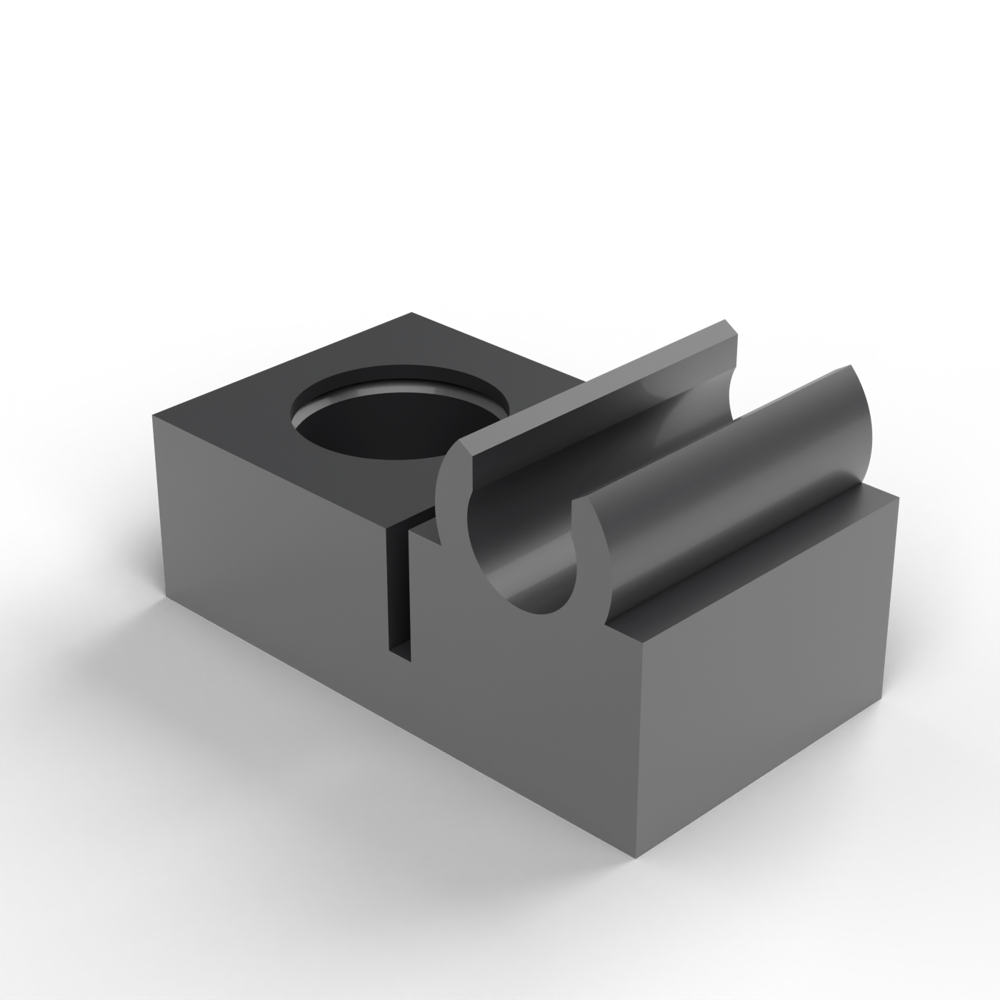 Image 2 of 4
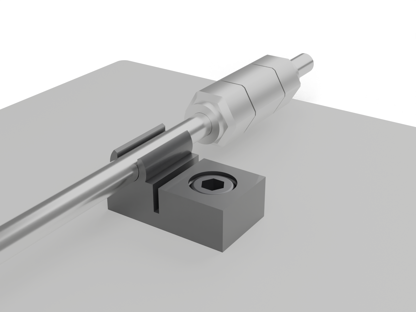 Image 3 of 4
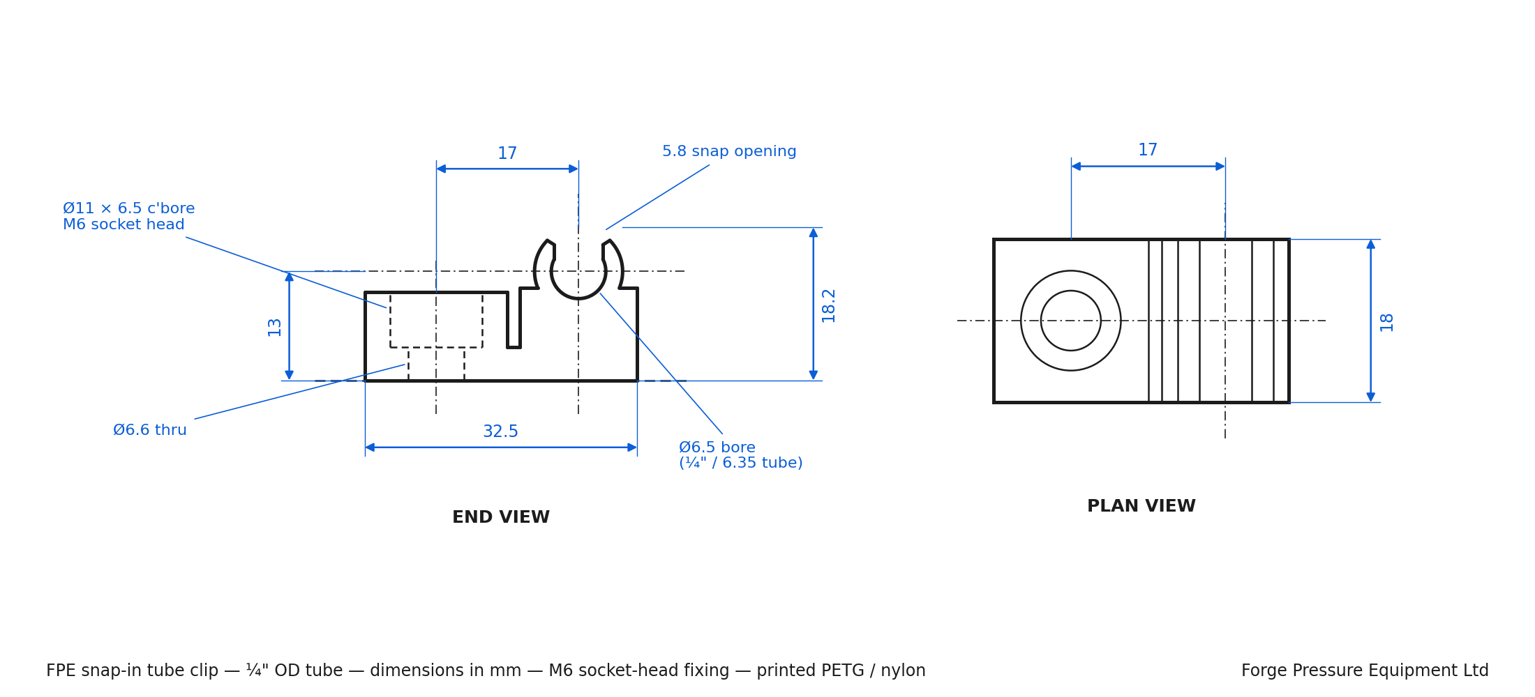 Image 4 of 4
Snap-in tube clips for instrument tubing — free STL download
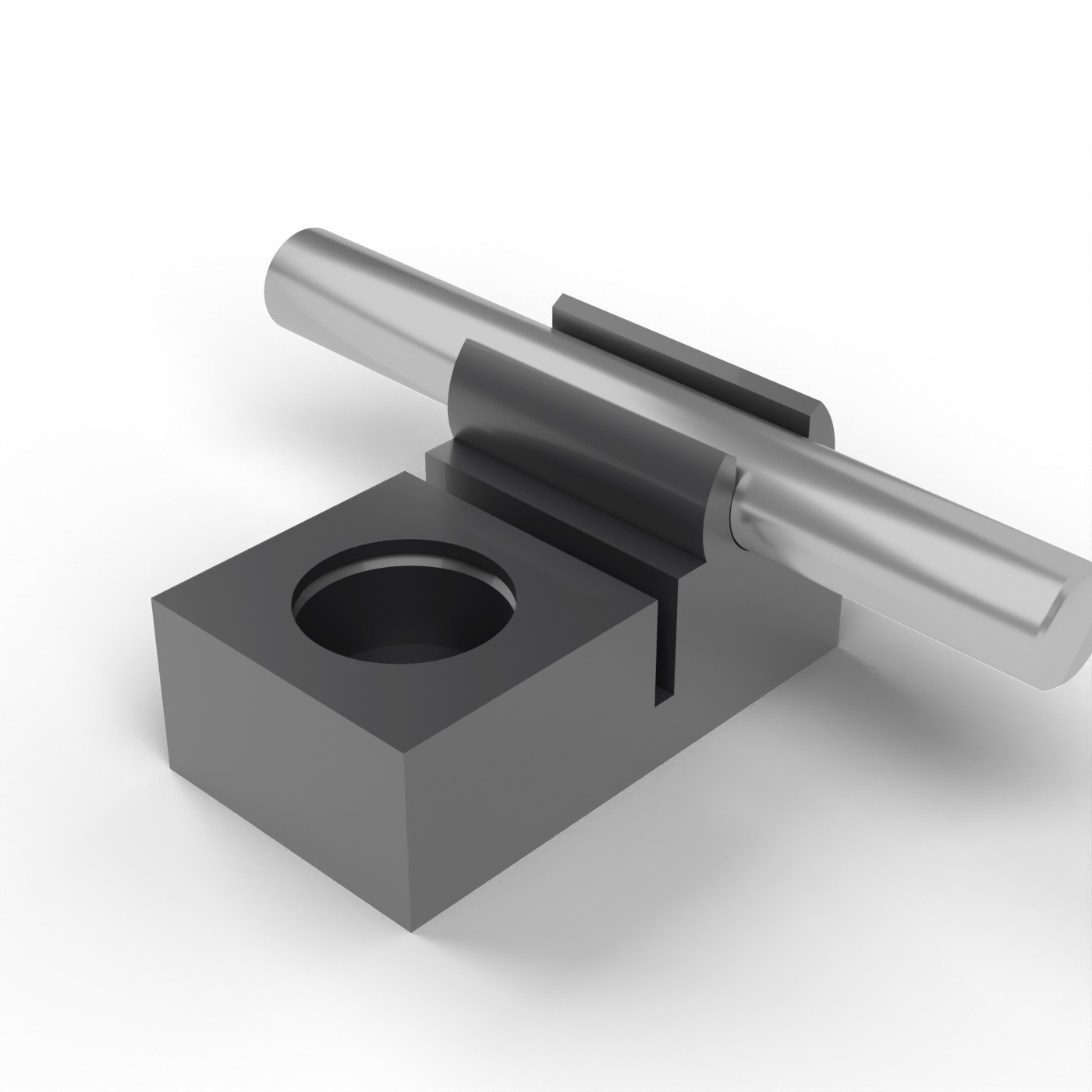
Panel clips for rigid instrument tubing, in six sizes: ¼", 3/8" and ½" imperial, and 6, 8 and 10 mm metric. The tube snaps into a sprung C-profile by hand, and each size holds the tube far enough off the panel for a standard compression nut or union body to sit hard against the clip without touching the mounting face — so a fitting can land right next to a clip without a spacer. A single M6 socket-head screw fixes the clip through an offset foot, leaving the screw head accessible with the tube in place, so clips can be added or moved without disturbing the pipework.
We designed these for our own gas panels and control enclosures at Forge Pressure Equipment, and use them on the equipment we build. They're free to download and print for your own use.
What's in the download
Six print-ready STLs, already oriented for the bed, and a dimensioned drawing for each size.
Sizes
Tube ODTube centreline above panelClears nutClears bodyClip size (W × H × L)Filament6 mm13 mm14 mm AF17 mm AF32.5 × 18 × 187 g¼" (6.35)13 mm9/16" AF11/16" AF32.5 × 18 × 187 g8 mm14 mm16 mm AF19 mm AF34.5 × 20 × 188 g3/8" (9.53)15 mm11/16" AF13/16" AF36.5 × 22 × 2010 g10 mm16 mm19 mm AF22 mm AF36.5 × 23.5 × 2010 g½" (12.7)18 mm7/8" AF1" AF40.5 × 27 × 2213 g
Every size: bore = tube OD + 0.15 mm, snap opening 91% of tube OD, Ø6.6 through-hole with Ø11 × 6.5 counterbore for an M6 socket-head cap screw, Ø6.6 panel hole. Nut and body clearances are to the hex corners, minimum 4.7 mm and 2.9 mm respectively.
Printing
Orientation: stand the clip on its end face, tube axis vertical, as supplied. This runs the layers around the ring so the snap arms flex across the print rather than along the layer lines. Do not lay it flat.
Material: PETG recommended — tough, tolerant of open-frame printers, 60 °C+ service. PLA prints easily but will crack at the arms after repeated tube insertion and softens near 50 °C. Nylon gives the best fatigue life if your printer is enclosed and the filament is dry. ASA for outdoor or UV exposure.
Settings: 0.4 mm nozzle, 0.2 mm layers, 4 walls, 40–100% infill, no supports. The counterbore prints as a horizontal hole; a fraction of a millimetre of sag at its crown is normal and harmless.
Fit: if the tube is slack in the clip, scale the model 99% in X and Y in your slicer; if the snap is too stiff, 101%. The 6 mm and ¼" clips differ only by 0.35 mm in the bore, so check the drawing if you have both tube sizes on the bench.
Fixings: M6 socket-head cap screw, 10 or 12 mm long, plus a nut or rivnut in the panel. Not included.
Licence
Free for personal and commercial use: print as many as you like for your own equipment, panels and installations, including equipment you build for customers, and share the files with credit to Forge Pressure Equipment Ltd. Please don't sell the files or printed clips as a product.
Please note
The clips are tube supports, not pressure-retaining or safety-critical components. Printed-part strength depends on your printer, material and settings, so check each batch before use. Dimensions are as modelled; measure your first print against the drawing.
Snap-in tube clips for instrument tubing — free STL download
Panel clips for rigid instrument tubing, in six sizes: ¼", 3/8" and ½" imperial, and 6, 8 and 10 mm metric. The tube snaps into a sprung C-profile by hand, and each size holds the tube far enough off the panel for a standard compression nut or union body to sit hard against the clip without touching the mounting face — so a fitting can land right next to a clip without a spacer. A single M6 socket-head screw fixes the clip through an offset foot, leaving the screw head accessible with the tube in place, so clips can be added or moved without disturbing the pipework.
We designed these for our own gas panels and control enclosures at Forge Pressure Equipment, and use them on the equipment we build. They're free to download and print for your own use.
What's in the download
Six print-ready STLs, already oriented for the bed, and a dimensioned drawing for each size.
Sizes
Tube ODTube centreline above panelClears nutClears bodyClip size (W × H × L)Filament6 mm13 mm14 mm AF17 mm AF32.5 × 18 × 187 g¼" (6.35)13 mm9/16" AF11/16" AF32.5 × 18 × 187 g8 mm14 mm16 mm AF19 mm AF34.5 × 20 × 188 g3/8" (9.53)15 mm11/16" AF13/16" AF36.5 × 22 × 2010 g10 mm16 mm19 mm AF22 mm AF36.5 × 23.5 × 2010 g½" (12.7)18 mm7/8" AF1" AF40.5 × 27 × 2213 g
Every size: bore = tube OD + 0.15 mm, snap opening 91% of tube OD, Ø6.6 through-hole with Ø11 × 6.5 counterbore for an M6 socket-head cap screw, Ø6.6 panel hole. Nut and body clearances are to the hex corners, minimum 4.7 mm and 2.9 mm respectively.
Printing
Orientation: stand the clip on its end face, tube axis vertical, as supplied. This runs the layers around the ring so the snap arms flex across the print rather than along the layer lines. Do not lay it flat.
Material: PETG recommended — tough, tolerant of open-frame printers, 60 °C+ service. PLA prints easily but will crack at the arms after repeated tube insertion and softens near 50 °C. Nylon gives the best fatigue life if your printer is enclosed and the filament is dry. ASA for outdoor or UV exposure.
Settings: 0.4 mm nozzle, 0.2 mm layers, 4 walls, 40–100% infill, no supports. The counterbore prints as a horizontal hole; a fraction of a millimetre of sag at its crown is normal and harmless.
Fit: if the tube is slack in the clip, scale the model 99% in X and Y in your slicer; if the snap is too stiff, 101%. The 6 mm and ¼" clips differ only by 0.35 mm in the bore, so check the drawing if you have both tube sizes on the bench.
Fixings: M6 socket-head cap screw, 10 or 12 mm long, plus a nut or rivnut in the panel. Not included.
Licence
Free for personal and commercial use: print as many as you like for your own equipment, panels and installations, including equipment you build for customers, and share the files with credit to Forge Pressure Equipment Ltd. Please don't sell the files or printed clips as a product.
Please note
The clips are tube supports, not pressure-retaining or safety-critical components. Printed-part strength depends on your printer, material and settings, so check each batch before use. Dimensions are as modelled; measure your first print against the drawing.